Menu Close

Category: SToRM32

New Products for STorM32!

WiFI NT Logger (beta)

loggers

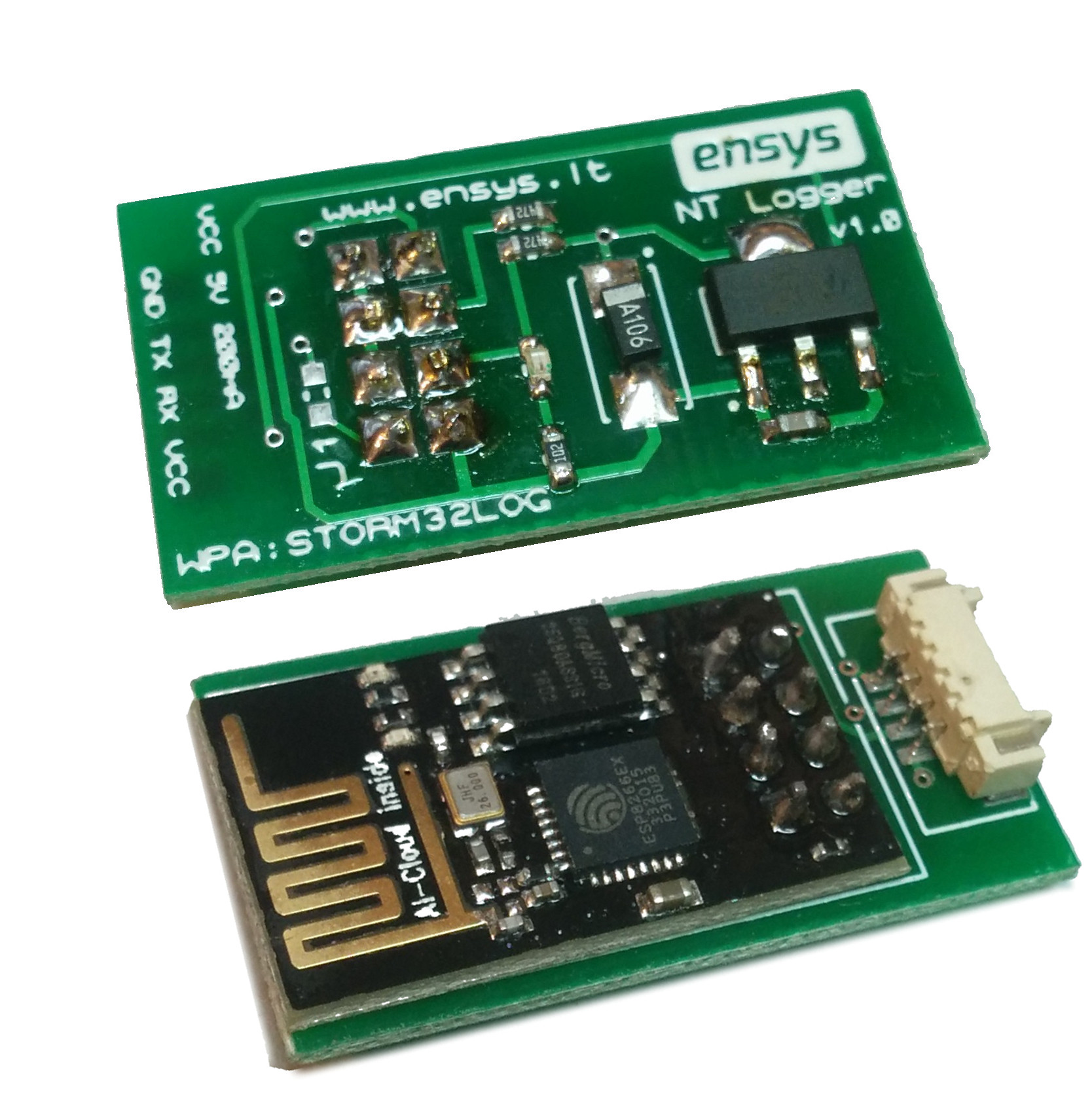
STorM32 WiFi NT logger is the go-to tool to debug STorM32 based gimbals. It records and sends full-speed raw data which is communicated on NT bus over WiFi. Data is collected with ENSYS Host tool. The host tool records data in .log file format which OlliW’s NTLoggerTool can load for analysis. Later versions of NTLoggerTool by OlliW will support real-time streaming from the ENSYS NT logger.
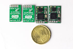
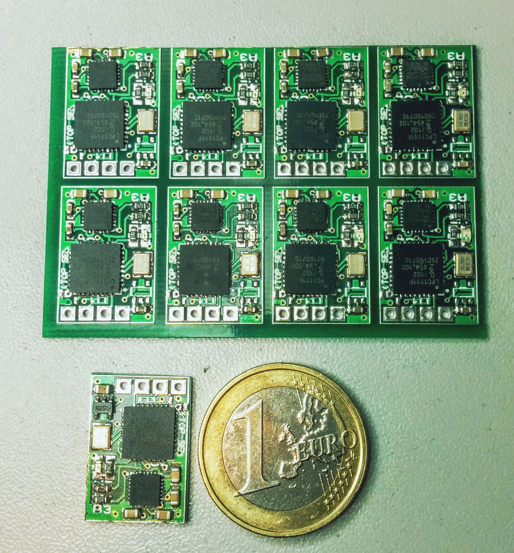
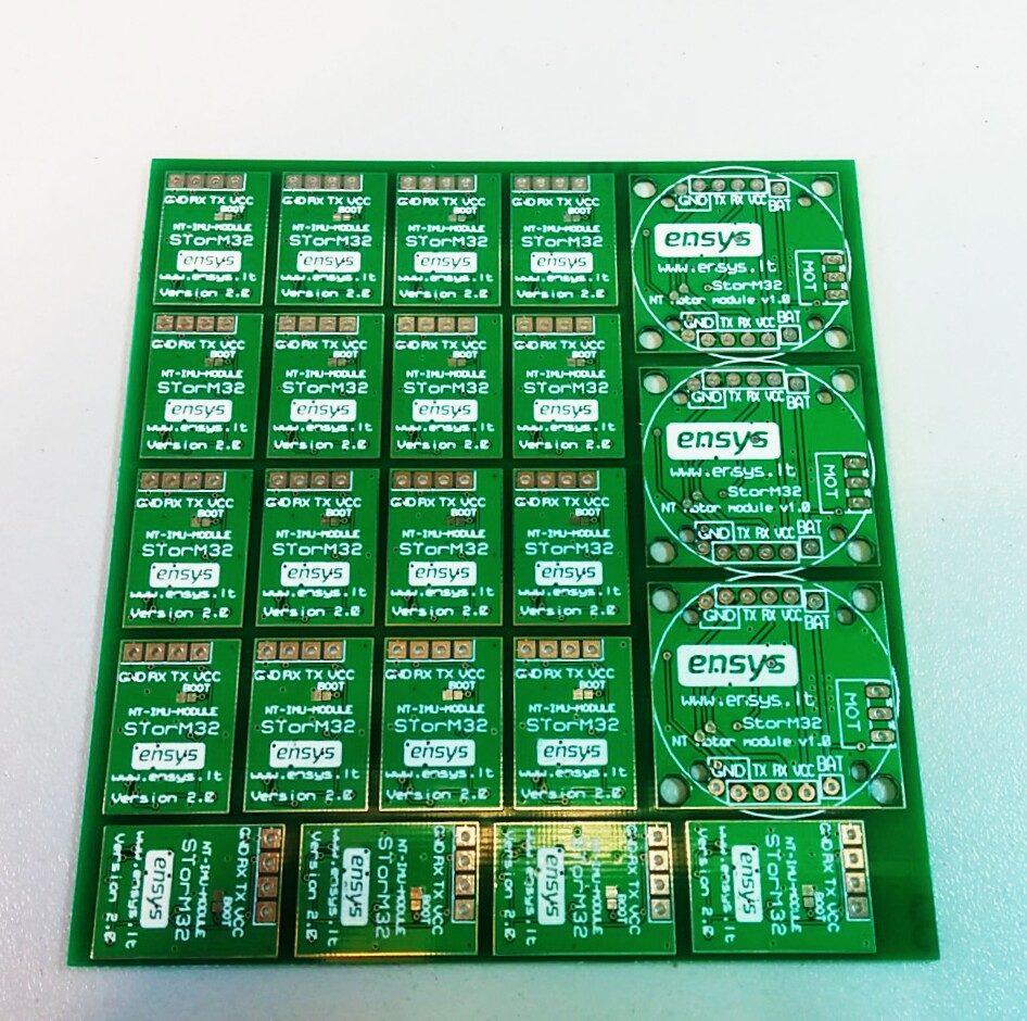
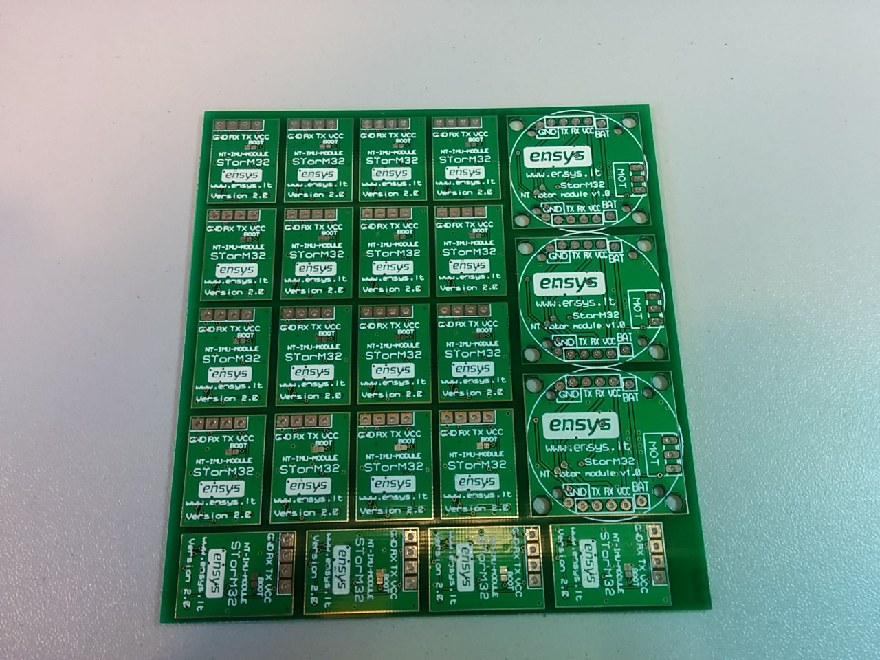
NT IMU Modules v2.5

imus

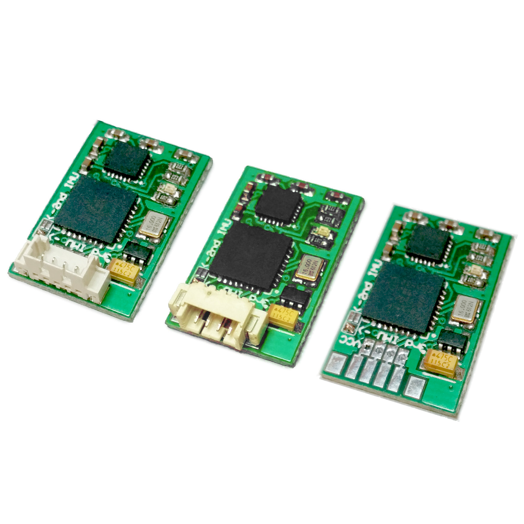
The updated design IMU modules now available. It’s now possible to customize the modules further – Choosing the connector type, calibration, including an additional wire.

LED Battery Indicator

batmon_front

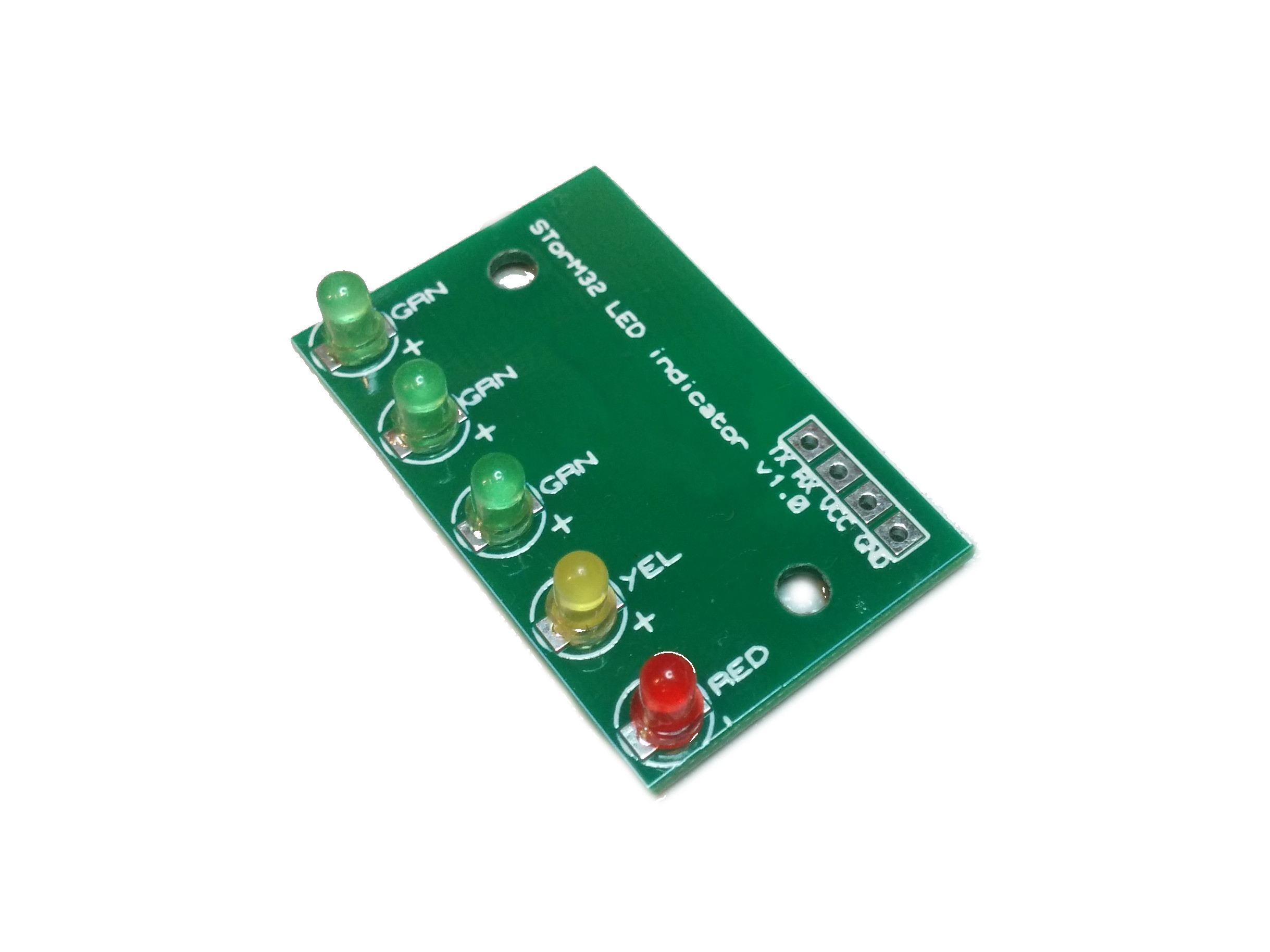
The LED battery monitor uses STorM32 controller’s UART port to retrieve battery voltage and display the state of charge using LEDs. This device accounts for voltage-charge non-linearity of lithium-ion/polymer batteries. It also displays the state of STorM32 controller. When the STorM32 is in SETTLE and LEVEL states the LEDs perform nice animations to indicate that the gimbal is calibrating.

IMU calibration service is now available

Hello, STorM32 users!

We now have IMU 6-point calibration service. When purchasing an IMU module you can now select an option to order a 6-point factory calibrated  IMU module, which will save you time when building your next gimbal! Calibrations are done in 25C room-temperature environment, therefore additional calibration using SToRM32 GUI utility may be neccessary if using the module in harsh temperatures.

The calibration data is stored inside the module, so no additional calibration is required – It’s plug and play!

Order now!

Everything about StorM32 NT IMU

BuyNow

Hello, before using our “ENSYS” V1.0 IMU’s keep sure you know everything about them. Literally, you can ask everything what is unclear for you.

Specifications:
– IMU Input voltage: 2 – 5.5 V.
– Compatible with StorM32 version: 2.03-NT and higher.
– Board dimensions: 17mm x 24mm x 2.1mm.

LED Status:
– 1 Hz blink – OK, bottom (camera) IMU setting.
– 0.5 Hz blink – OK, top IMU setting.
– 5 Hz fast blink – Error status. The controller is unable communicate with MPU6050 chip.

Top/Bottom IMU settings:
Module works as bottom (camera) IMU by default, to set it as TOP IMU, solder bridge (showed in photo) should be shorted. If you require to get TOP IMU, write message while ordering, we will short it.

Important note:
Version 1.0 module has an error on the back silkscreen print which says “VCC RX TX GND” it should be reversed: “GND RX TX VCC”. Your responsibility if you connect it in wrong way.

Firmware Updates and Info:
Storm32-NT-IMU is tested with newest firmware. There is no new version at the moment.

Flashing:
Instructions will be provided when new version will be released.

Package:
– StorM32 NT IMU CHIP with newest firmware.
– No additional wires.

Christmas came early this year

Today we received a batch of PCBs which we ordered about three weeks ago. After first successful sellout of NT bus IMUs for SToRM32 brushless gimbal controller, we decided to shrink the NT IMUs from 24x16mm to 20x14mm which makes these possibly the smallest NT IMUs in the world (that I know of) at the time of this writing.

Another good news we have received a prototype board for STorM32 NT Bus motor driver which will need some programming love soon enough. It will have an LPC1111 microcontroller at it’s heart and a DRV8313 as a brushless motor driver.

As for NT IMUs, we started soldering them and they will be available in our shop very soon for sale. Preorders are welcome.

NT PCBs

IMG_20160609_165304